Making Fruit Ninja in real life with a laser sword
A project involving fast image processing, projective geometry and lasers.
A while ago now, I designed and developed a "gaming experience" involving Fruit Ninja and a laser sword, which is best explained by watching the video below.
To put it into words, the player has a sword with dynamic LED lighting and a laser on the end. The wall has a game (in this case, a Fruit Ninja clone I made) projected onto it, and pointing the laser at the wall allows the player to interact with the game, which in this case is slicing the fruit.
Behind the scenes though, this took a lot of tech and a lot of development. All of the equipment I used is on this desk, which I’ve labelled.
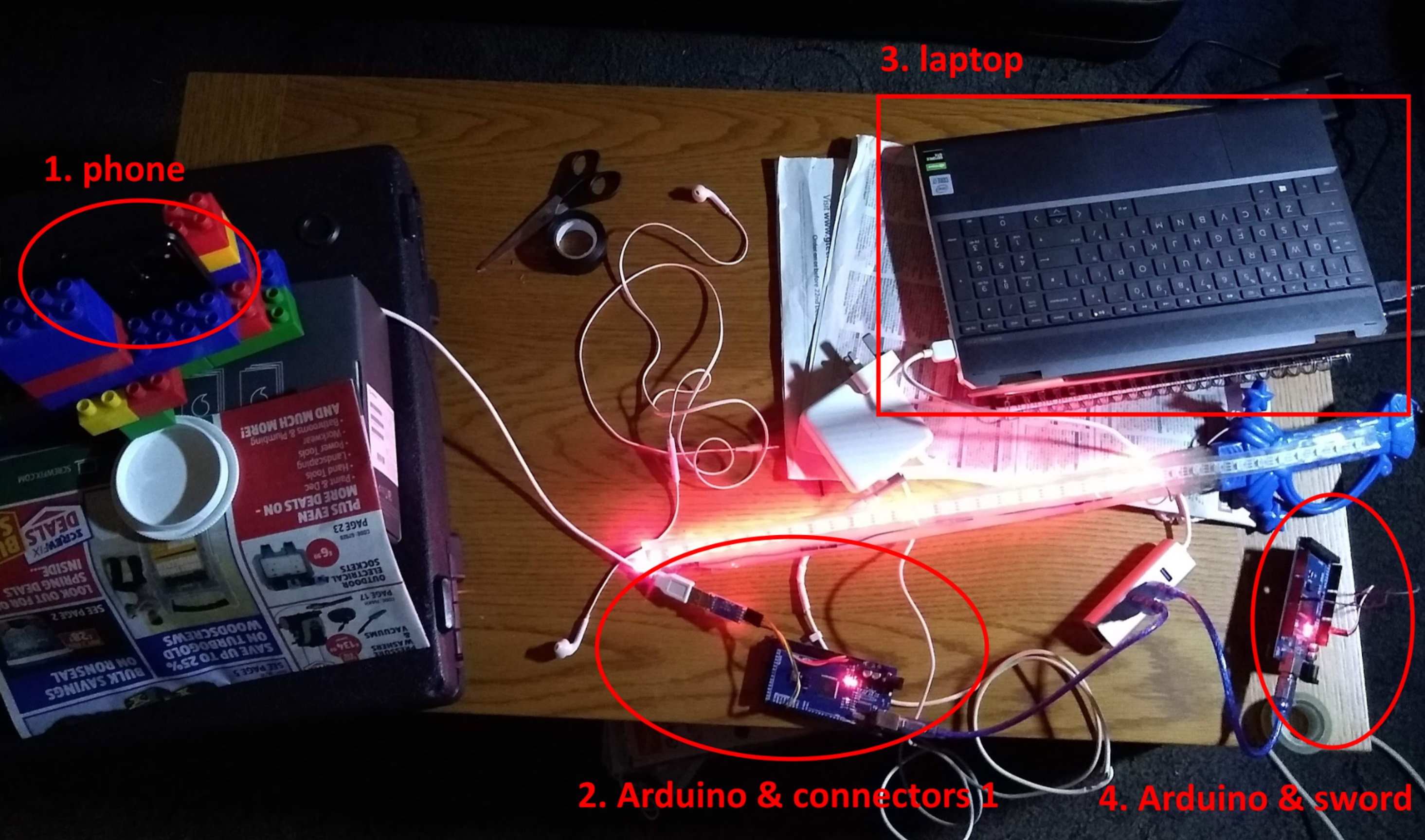
Let’s go through each of the pieces step by step.
Number 1: Phone and laser position capture
The way I decided to identify the laser position was by creating a Cordova app that accessed the phone camera. The camera is pointed at the projected screen to find where the laser point is. However, even such a seemingly simple task has many complex steps.
In this subproblem, the input is a stream of frames from the camera, and we need to extract the laser position from the frames to output a laser position. All of this needed to be done at a high rate (60 frames per second) on large input frames (1920x1080).
Before we can do anything, we need to get the camera data into a video element, which I’ve done using this code:
navigator.mediaDevices.getUserMedia({
    video: {
        facingMode: 'environment',
        width: {
            min: x
        },
        height: {
            min: y
        },
        frameRate: {
            min: 60
        }
    }
}).then(gotMedia, failedToGetMedia);
function gotMedia(mediastream) {
    //Extract video track.
    let videoTrack = mediastream.getVideoTracks()[0];
    console.log(JSON.stringify(videoTrack.getCapabilities()));
    video.srcObject = mediastream;
    video.play();
}
Initially, my plan was to use a component from machine learning called convolutional filters. I have previously discussed these in my article on ASCII video, but in summary, this is a set of weights and biases that can be applied to the immediate neighbourhood of each cell to assign each cell a “score”. This score will be “how likely is this point to be a laser”, or in more technical terms, “how similar is the 5x5 point around the current pixel to the average 5x5 point around a laser dot”. Then, I can take the highest scoring point and set it to the current laser position.
I initially implemented this using Tensorflow JS to perform computation. Under the hood, it uses the phone’s GPU to perform many processes in parallel. Initially, I was quite hopeful, as Tensorflow’s benchmarking said that it took 13ms to make a computation on one frame, which is easily fast enough to get laser positions 60 times a second. However, when I tried to extract the data from the computation into a JavaScript array, it turned out that the whole computation took 100 milliseconds, which was much too slow. I spent way too long trying to reduce the computation time, but eventually I gave up and was forced to approach this from another angle.
I struggled to find any conclusive reasons for why there was this discrepancy in timing, but I had some theories that could explain this:
- The GPU is using a queue: the time being reported is the time required to put all of the instructions to find the laser position in a queue for the GPU to process. It takes longer to extract the data from the GPU as we are actually waiting for the whole queue to go through
- Our computations are too complex
- Tensorflow itself is adding some large overheads, and isn’t performing the operation as quickly as it could be performed directly.
To solve these issues, I significantly scaled back my computation and began directly using WebGL.
To scale back my computation, I started using the brightest pixel in the image as the laser position. I set the phone’s camera to have a very low exposure. As I am projecting the image onto a wall, the “screen” is almost black on a low exposure, and the red laser is reduced to a very small dot.
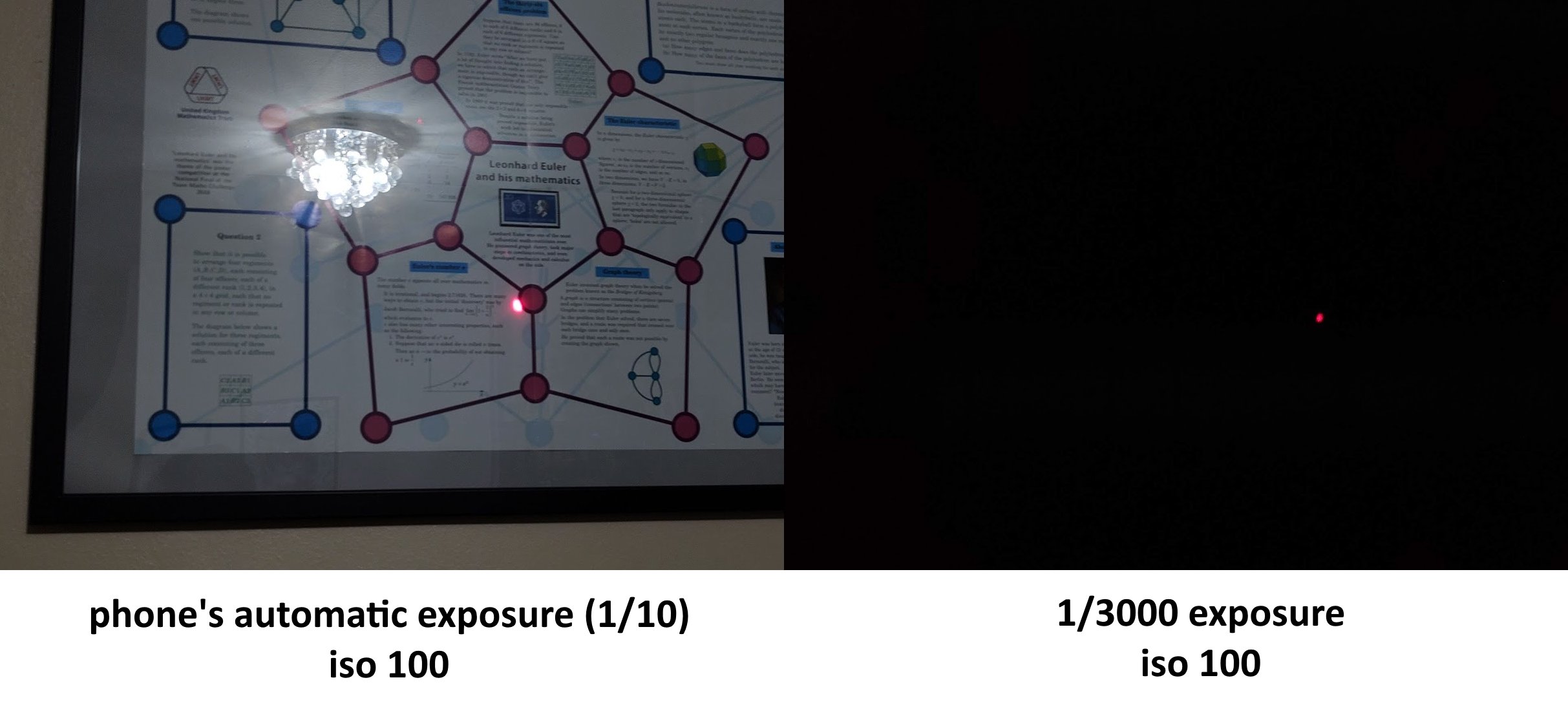
Now, I just need to find the brightest pixel on the screen. However, using WebGL, I’m quite restricted in what I can do, since WebGL isn’t intended for computation - it’s intended for drawing graphics. To use WebGL in the browser, one needs to create a canvas onto which to draw. I then use “shaders” to perform computation. These are small programs written in a language called GLSL, and their purpose in this implementation is to tell each output pixel what color it should be. I can pass image data into these shaders as well (these are called textures).
Now to find the brightest pixel in a 1920x1080 image, I create a WebGL canvas of size 1920x2. Each output pixel encodes the brightness and location of the brightest pixel out of the 540 it is “assigned” to. This is more clearly illustrated in the image below:
![]()
The shader code I used is below
#version 300 es
precision highp float;

uniform sampler2D srcTex;
out vec4 outColor;

void main() {
    ivec2 texelCoord = ivec2(gl_FragCoord.xy);
    float maxVal = -10000.0;
    vec2 maxPos = vec2(0, 0);
    for (int i = 0; i < ${y / 2}; i++) {
        vec4 currPix = texelFetch(srcTex, ivec2(texelCoord[0], i + (texelCoord[1] * ${y / 2})), 0);
        float val = currPix[0] + currPix[1] + currPix[2] + currPix[3];
        if (val > maxVal) {
        maxVal = val;
        maxPos[0] = float(texelCoord[0]);
        maxPos[1] = float(i + (texelCoord[1] * ${y / 2}));
        }
    }
    outColor = vec4(mod(maxPos[0], 256.0) / 255.0, mod(maxPos[1], 256.0) / 255.0, (((maxPos[0] - mod(maxPos[0], 256.0)) / 256.0) + ((maxPos[1] - mod(maxPos[1], 256.0)) / 16.0)) / 255.0, maxVal / 4.0);
}
The key point in using all of these shaders and canvases and pixels is that WebGL can run our shader on every pixel of the output image in parallel. With the output canvas dimensions above (which were what I determined to be the fastest after a lot of testing), the potential speedup from this is 3840 fold.
We still aren’t done in finding the brightest pixel. I then read the pixel data off of the WebGL canvas into a JavaScript array. *(I could have used another canvas with another brightest-pixel-identifying step to leave only one pixel containing data on the location of the overall brightest pixel, but this turned out to be slower). In JavaScript, I looped through all 3840 output pixels (which is a lot less than the 2 million in the initial image) to then find definitively, the overall brightest pixel. As each output pixel tells us the position and brightness of the 540 pixels in the input image that it is assigned to, we can see which output pixel contains data for the brightest input pixel, and then finally also extract the brightest input pixel’s location.
This entire process completes in about 17 milliseconds, giving an overall frame rate of almost 60fps.
Phew! Who would have thought that efficiently finding the brightest pixel would be such a lot of work?
Even then, we still aren’t done. We need to convert the position of the laser in the image into a position of the laser in the game canvas. As the phone camera is at an angle to the wall, rectangles such as the rectangle of the projected game become very distorted, as shown below.
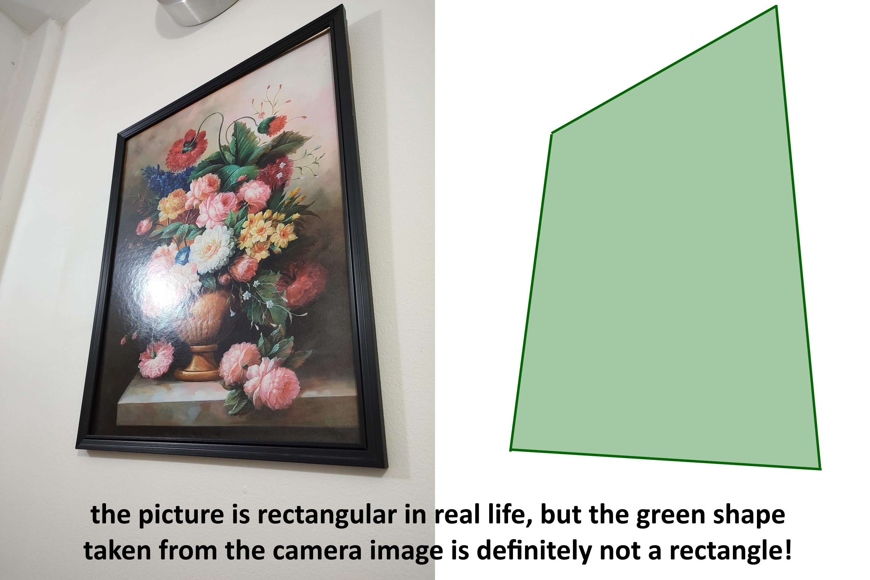
I need to correct this distortion in order to find the position of the laser in game coordinates.
To do this, I’ll be using something called projective geometry. Projective geometry deals with projections of the plane and lines in it into new lines - essentially a projection in projective geometry is a transformation of the plane that has a 1 to 1 mapping between points and lines in an old and a new plane, which is exactly what is going on here.
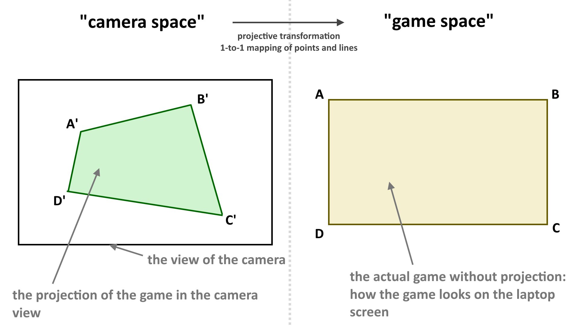
Before we carry on any further, we need to talk about cross ratios. A cross ratio is a quantity that can be measured for 4 ordered points that lie on a line, and for points ABCD their cross ratio (denoted as (A,B; C,D)) is: \(\frac{AC \cdot BD}{BC \cdot AD}\). On its own, this seems like a very arbitrary quantity. However, its true power is that cross ratios are preserved under projections of the plane.
Using just the fact that cross ratios are preserved, we can actually find out where a point X is in relation to the game space ABCD given its position X’ in camera space, where A’B’C’D’ is the projection of the rectangle of game space into camera space. The following diagram is used to illustrate how this is done.
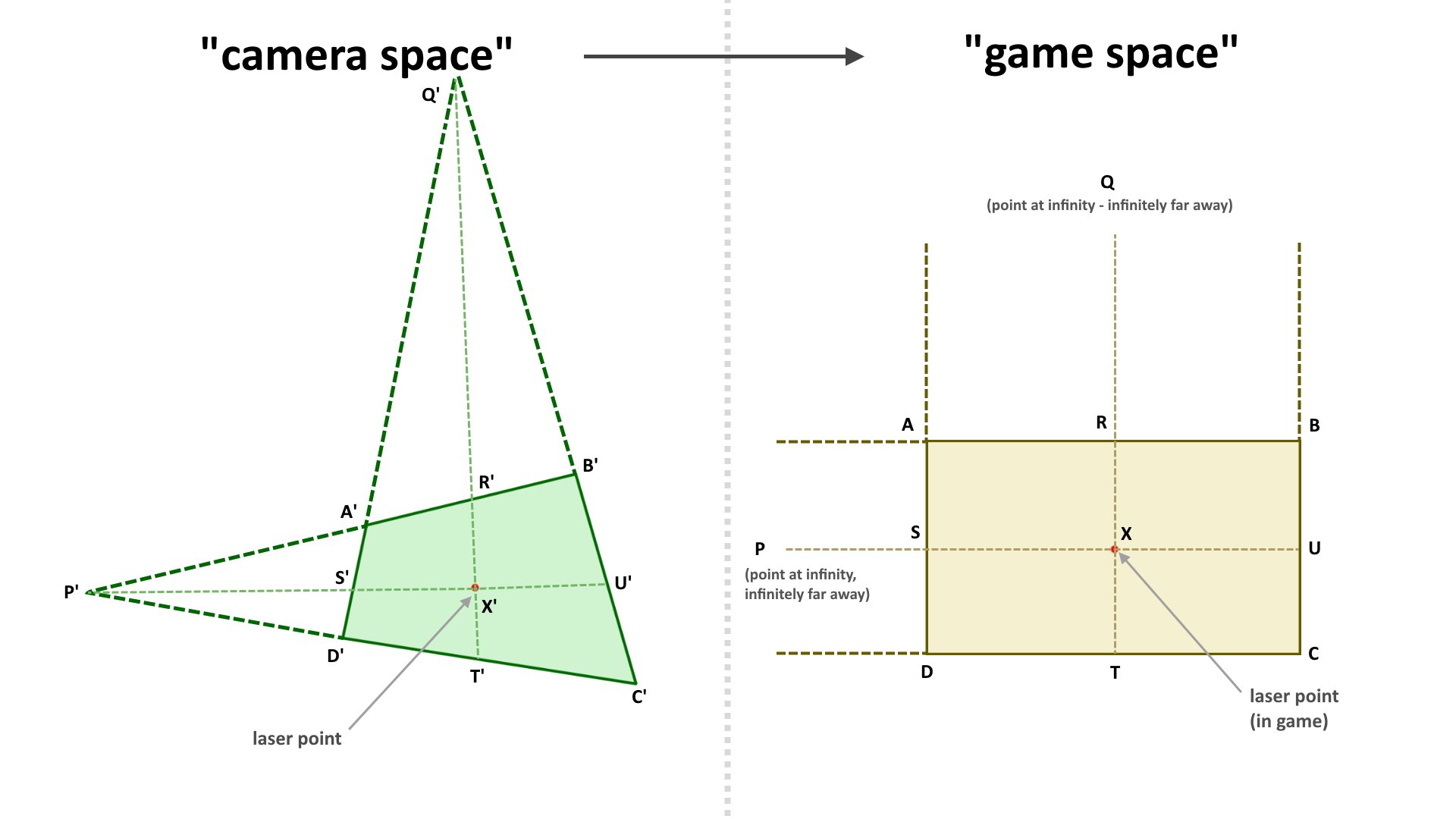
Now as we know that cross ratios are preserved, we know that \(\frac{Q’X’\dot R’T’}{R’X’\dot Q’T’} = \frac{QX\dot RT}{RX\dot QT}\). However, as Q is infinitely far away, QT = QX (as both of these values are infinite), so \(\frac{Q’X’\dot R’T’}{R’X’\dot Q’T’} = \frac{RT}{RX}\). As we know \(\frac{RT}{RX}\), and we know the height of the game (\(RT\)), we now know \(RX\), which is the y-coordinate of the laser point in the game.
We can do a similar thing with the cross ratios of (P,S; X,U) and (P’,S’; X’,U’) to get the x-coordinate of the laser point in the game.
To implement this in practice, I added a calibration function to the app. To use the calibration, the user would have to point using the laser at all four corners of the game screen (A’B’C’D’) so that the application knows where the game screen is. From there, it can “reverse” the projection to find out where the laser is in relation to the game.
2. Sending the laser position over
At first, I wanted to directly run the game on the phone. Unfortunately, my phone at the time did not have the capabilities to display its screen on the projector over USB-C, so I would not be able to run the game on the phone. Instead, I would have to run the game somewhere else, and this is where the laptop comes in. The laptop will do all of the heavy lifting of rendering a game and its UI.
However before I can do that, I need to somehow communicate where the laser is to the laptop. I decided to do this over serial. I’m not an expert on the intricacies of serial communication (yet), but when I tried to directly send serial data over a USB cable to my laptop, my phone didn’t recognise my laptop as a place it could send data to. I then rewired everything to go through a USB-to-TTL converter, then into an Arduino that relayed the serial data, then straight into my laptop. With this setup, the phone was able to recognise the USB-to-TTL converter as a “device” it could communicate with, and the laptop recognised the Arduino as a device it could accept data from.
That wasn’t the end of my issues however. I found that laser position data seemed to strangely come in batches of 2-4 frames every 30-60 milliseconds, which would make the game seem very choppy. Luckily, increasing the baud rate to 115200 easily fixed this issue.
3. Running the game
At this stage, the laptop now has the coordinates of a laser point, but nothing more.
So let’s make a fruit ninja clone!
This isn’t a very technically complex project, but I’ll go over the key steps.
First, I need fruit to slice. I went ahead and sketched five fruits by myself in paint. I also drew the fruits sliced into halves. I also added two “bonus fruits”. The “Freeze Banana” would slow down the passage of time, while the “Frenzy Banana” would spawn extra fruit and negate any misses during its effect duration.
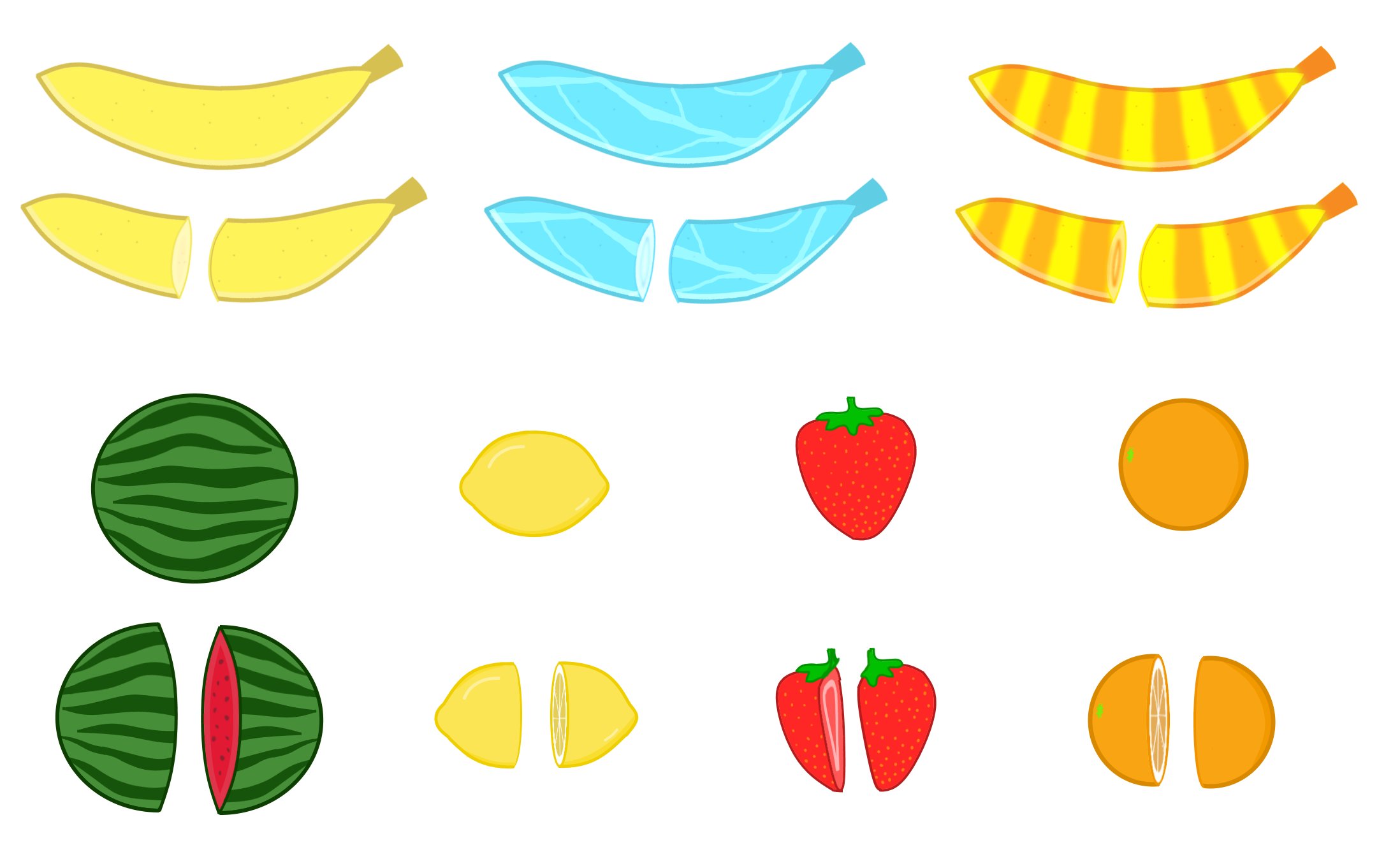
This provided the base assets for most of the game.
From here, I run a standard loop using requestAnimationFrame to render each frame. When I render each frame, I run through a long checklist of things to do in order:
- Spawn any new fruit if we should be spawning fruit this frame
- Draw the background of the game
- Draw any splashes of previously cut fruit
- Check for slices. To do this, I look at the path of the laser pointer between the current frame and the frame before. I then see if this path cuts through the “hitboxes” of any fruit on the screen. If so, I slice the fruit into its two halves.
- Draw all fruit currently in the game
- “Update” all fruit: each fruit needs its position to be incremented by its velocity and its velocity to be incremented by the global acceleration of gravity. It also needs its current rotation to be incremented by its rotational speed.
There are quite a few more complexities to talk about here (scoring, levels, power-up fruit, effects when fruit are missed, adding sound effects for everything, bonus points for combos, spawning fruit with a rate that increases according to level), but all of this isn’t very technically complicated.
However, one important technical complication is latency correction. After I had implemented the whole game and began to test it with the laser capture system, I realised that the laser point in game lagged behind the laser point in real life. Upon further investigation, I realised that this latency occurred due to:
- Latency between the camera feed on the camera feed and real life on the phone camera. You can try this yourself with a phone camera! Hold your hand still in front of a phone camera, and then suddenly move it out of view. You’ll find that the hand will persist for a while longer on the screen
- Latency in HDMI from the laptop to the projector
- Latency in communication between the phone and the laptop.
All of this added up to about 200ms of latency. This meant that while you were playing the game, moving the laser in real life over a fruit would almost never slice a fruit.
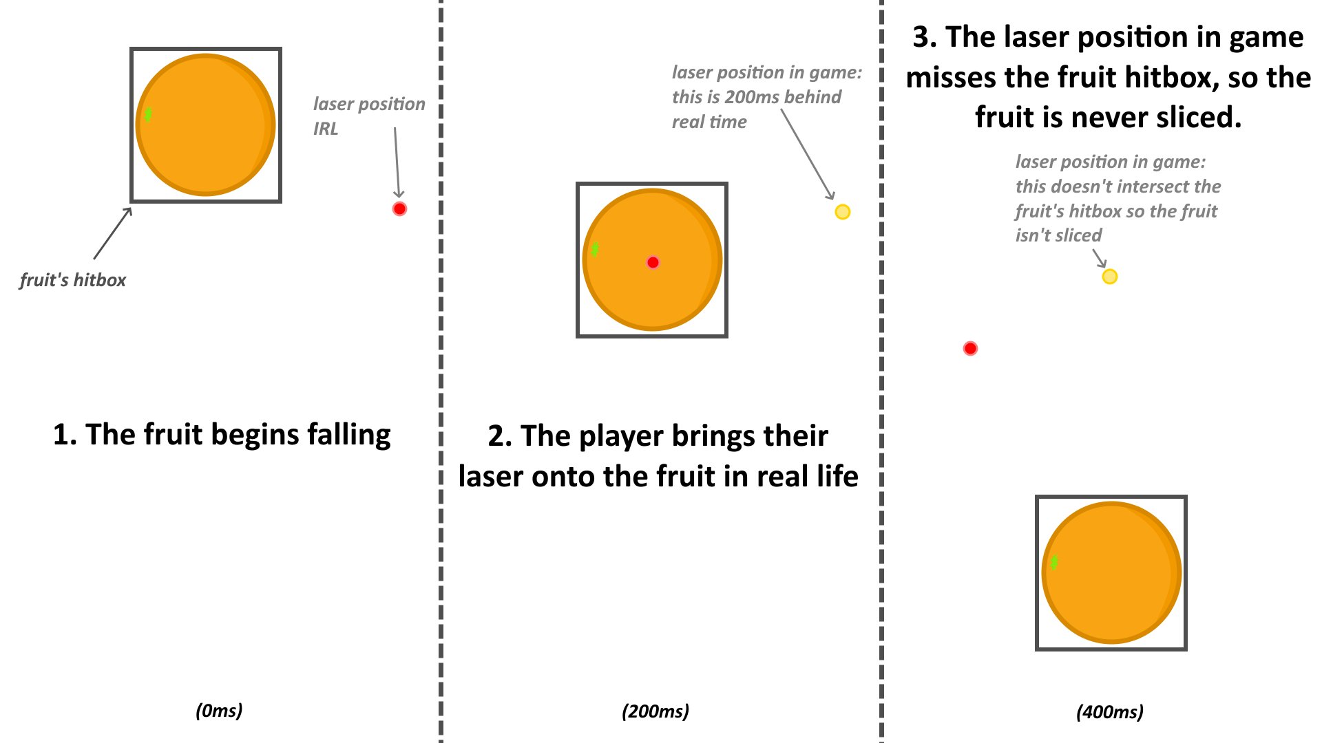
The player would have to look at a red dot in the game that represented where the game thought the laser was, and account for this latency while moving their sword. Essentially, the player had to put the sword where the fruit would be, not where it currently was. All of these issues made for quite a frustrating gaming experience. I thought about using a Kinect camera instead, but my Xbox360 Kinect camera didn’t have the exposure control I needed and it also seemed to have its own significant latencies.
Instead, I used a trick that I’m going to call hitbox rewinding. If the latency is fixed and measured beforehand, this would allow the game itself to adjust for the latency in updating the laser point.
Here’s how it works:
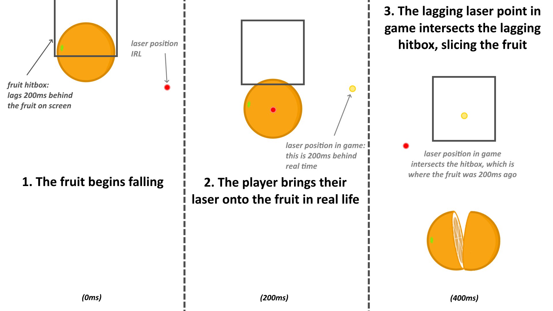
In words, I make the fruits’ hitboxes lag behind their current position in the real world. This means that when the game’s position of the laser catches up to where the fruit previously was, it will slice the fruit as the fruit’s hitbox is lagging behind.
I do this in practice by allocating memory for a small “history” of hitbox positions. When checking if the laser is passing through the fruit, it doesn’t look at the current fruit hitbox position and instead “rewinds” to try to find the hitbox position 200ms (12 frames) ago.
The end result of this is that there is still a 200ms delay between passing the laser over a fruit and slicing it, but if the player passes their laser over a fruit, it will always slice. This removes a lot of the frustration while playing, and lets players play much more freely instead of trying to adjust for a hidden delay.
4. Sword effects
Finally, to wrap the game up, I needed a laser sword. Until now, I had been testing everything with a small laser pointer, but that’s no fun.
I took an old plastic sword, and first glue-gunned a 5mW laser to the end of it. I strung wires all the way down to the handle. I also stuck a 1m WS2812B LED light strip around the whole sword as well. This was all a bit of duct-tape job, but it held together surprisingly well.
Originally, I wanted to put an ESP32 and a powerbank in the sword handle to control the light strip. However, I was having serious powering issues when trying to control more than 15 LEDs of the light strip with the ESP - the lights would flicker a lot, and this worsened when I used a power bank instead of my laptop supply. I thought this had something to do with the 3.3V logic level of the ESP not being registered as a “HIGH” in the WS2812B logic, but even after using a homemade transistor-based logic level converted to increase 3.3V to 5V, I still had no success. If anyone knows how to
In the end, I gave up on making the sword wireless and used an old cable to supply 5V, GND and data (for the light-strip) to the sword, and just used a reliable Arduino as the controller.
The reason I wanted a light strip in the first place was so that I could make the lighting react to the power-ups in the game. The lights would be red by default, but they would pulse blue while the “Freeze” power-up was active and they would pulse orange when the “Frenzy” power-up was active. You can see this clearly in the video at the top of this page.
To link the lights to the game, I sent what power-ups were active every frame over serial to the Arduino controlling the light strip. The Arduino then had all of the logic of creating the special effects in the sword.
Next steps
And with that, my project was complete! Me and my family had a lot of fun playing with the finished product, but it could definitely be improved in many ways.
The most obvious one is getting a camera upgrade so that I can process the inputs with lower latency, so that I don’t have to do any hitbox rewinding. This would allow me to make many more games. I would also like to add a button to the sword so I could turn the laser on and off - the two improvements above would allow me to turn my laser sword into a laser gun in an aim training game!
In a perfect world, I could package all of this into a “laser games console” that you could use like a regular console, except that the games would use this laser input.
This was very time consuming, but a lot of fun to work on :)